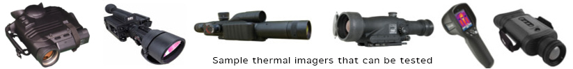
Thermal imagers
Thermal imagers (synonyms: FLIR, thermal camera, thermal imaging system, thermal viewer, thermovision) are imaging systems sensitive to mid-wave and long-wave infrared radiation that generate images of the observed scenery using thermal radiation emitted by the scenery. They are one of the crucial surveillance technologies for the defense/security sector. These imagers have also found mass applications outside the defense sector. Testing thermal imagers is needed for both manufacturers, maintenance workshops, and final users for a set of different and important reasons. Hi-tech test equipment can help significantly in research and development, manufacturing, maintenance, training, purchase optimization, and optimal use of these expensive imagers.
Thermal imagers are characterized using a long series of parameters. The most popular are: MRTD (Minimum Resolvable Temperature Difference), NETD (Noise Equivalent Temperature Difference), MTF (Modulation Transfer Function), FOV (Field of View). MRTD is a function of a minimum temperature difference between the bars of the standard 4-bar target and the background required to resolve the thermal image of the bars by an observer versus spatial frequency of the target. NETD is a measure of high-frequency temporal noise of the image generated by the tested thermal imager. MTF is a function that describes sharpness (blurring) of the image generated by the tested thermal imager. Finally, FOV is a parameter that describes the maximum angular size of a target that can be seen by the tested imager. More detailed definitions and measurement methods of thermal imager parameters are presented in the Educational section.
Nowadays, thermal imagers are manufactured in large quantities and variations by many manufacturers. They can be classified according to several criteria: application (surveillance or measurement), spectral band (MWIR or LWIR), FPA sensor type (cooled or uncooled), field of view correlated with the aperture of the camera optics (from a very narrow FOV below approximately 0.5° to a very wide FOV over approximately 50°), image resolution (from about 160x120 or below to 1900x1200 pixels), electronic video signal format (analog or digital), display type (external or internal), and the mechanical format of the device (thermal cameras, thermal sights, thermal clip-ons).
It is not possible, or at least it is not feasible, to design a single universal system for testing all thermal imagers offered on the market that differ significantly from one imager to another. Therefore Inframet offers a series of systems optimized for testing different groups of thermal imagers.
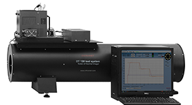
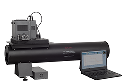
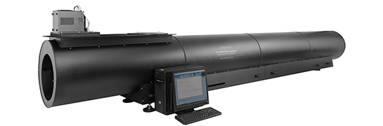
DT is Inframet's most popular quasi-universal system for testing thermal imagers used in hundreds of laboratories worldwide. DT test systems enable extensive testing of almost all thermal imagers available on the market.
a)
|
b)
|
c)
|
|
| Fig.1. Several DT systems: a) DT15120, b) DT11100, c) DT40400 | |
Inframet also offers additional specialized systems for testing specific types of thermal imagers:
- TAIM for extended testing of portable sights/clip-ons,
- TAFT is a mobile test station designed to enable basic testing of surveillance thermal imagers in field/depot conditions,
- TCLIP - system for basic testing of thermal clip-ons that enables fast checking of proper alignment,
- DTR - system built using a refractive collimator optimized for testing small thermal imagers of very wide FOV,
- TSIM - simple, low-cost system designed to enable only basic tests (focusing and resolution measurement) of thermal imagers,
- SAFT - small test system for testing measurement thermal imagers designed for short focal distance,
- TWAP - a portable wide-angle projector optimized for testing imagers of medium/wide FOV,
- TCAR - system for testing automotive thermal imagers.
a)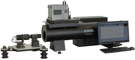
|
b)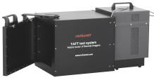 |
c)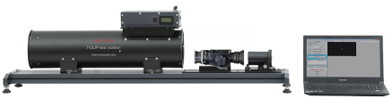
|
d)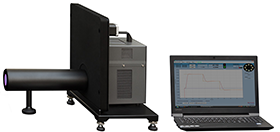
|
e)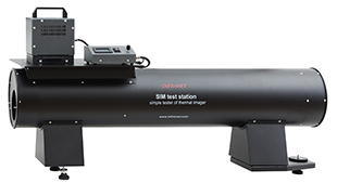
|
f)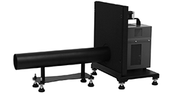
|
g)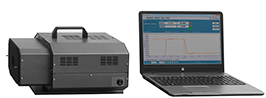 |
h)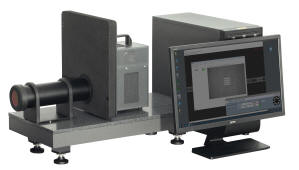
|
Fig.2. Photos of additional test systems: a) TAIM, b) TAFT, c) TCLIP, d) DTR, e) TSIM, f) SAFT, g) TWAP, h) TCAR
NON-UNIFORMITY CALIBRATION
Application of image processing algorithms capable of correcting spatial noise of the IR FPA sensor of a thermal imager is of critical importance for designing thermal imagers capable of generating near noise-free thermal images. Data needed to develop such algorithms is acquired during so-called two-point NUC (non-uniformity correction) tests, when the calibrated camera views a large blackbody filling its FOV at two different temperatures. In the case of advanced thermal imagers, NUC tests are carried out in a temperature chamber at different ambient temperatures that resemble real operating conditions.
There are many low-cost blackbodies offered on the international market that can be used for two-point NUC applications. However, due to significant specular reflectivity, noticeable thermal non-uniformity, limited temporal stability, and lack of ability to operate in temperature chambers, these blackbodies are not suitable for professional applications. Inframet offers BNUC sets of blackbodies optimized for professional two-point NUC applications.
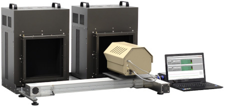
Fig.3. Photo of BNUC-12D-2TCB-TC blackbody set
TESTING IR CAMERA CORES
A thermal camera core is an electronic module capable of generating an output thermal image in one of the standard video formats. It is built as a raw IR FPA sensor integrated with control/processing electronics. In simplification, a thermal camera core can be understood as an almost complete thermal imager without optics. Thermal camera cores are crucial building blocks of thermal imagers constructed by combining a camera core, optics, and a mechanical housing. There are some companies that manufacture all these main blocks (camera core, optics, and mechanical housing) and later build complete thermal imagers. However, the majority of thermal imagers offered on the international market are built using thermal camera cores purchased from a dozen main manufacturers. In such a situation, the problem of performance testing of thermal camera cores is of crucial importance for manufacturers of thermal imagers who work as system integrators. The test range is typically limited to measurement of NETD (noise equivalent temperature difference), which is considered a crucial parameter and is needed to verify the quality of purchased camera cores. Other noise parameters such as FPN, non-uniformity, and 3D noise model are sometimes measured as well. All these noise parameters of camera cores are measured and presented for a specific reference optic, and this optic must be simulated during tests.
DTCORE is a set of tools designed for testing thermal camera cores. It is typically offered as an option for DT systems for testing thermal imagers. It enables measurement of the following parameters: NETD, FPN, non-uniformity, and 3D noise model. DTCORE is a modular set built from the following modules: a pair of OIM optics imitators, TCB-4D blackbody, PC set, analog video frame grabber, TCB control program, and TAS-N computer program. The OIM optics imitators are a crucial part of DTCORE. From a design point of view, OIM imitators are mechanical devices that precisely limit the cone in which the camera core sensor receives radiation from a large blackbody of variable temperature to a value determined by the F-number of the simulated infrared objective.
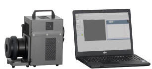
Fig.4. Photo of DTCORE set
Learn more:
- Data sheets: DT, TAIM, TSIM, DTR, TCLIP, TAFT, TWAP, TCAR, SAFT, BNUC, DTCORE
- Customer questionnaires for systems for testing thermal imagers
- Recommendations on environmental conditions for Inframet test systems
- Educational section
- E-book: TESTING THERMAL IMAGERS
- Inframet Info section
- Inframet Newsletter
- Contact INFRAMET