Boresight
Boresight is probably the most ambiguous term in electro-optical metrology. It is often used by many people who understand it in different way or do not know at all its precision interpretation. It is quite common for Inframet to get a request for delivery of a test system capable to do boresight of an electro-optical imaging/laser system without any precision information what is to be done.Next, some of our potential customers ask for delivery of test systems capable to check proper boresight of itself. Finally, there are customers who want to be able to check relative boresight of the collimator of the test system relative to external reference mechanical/optical block. In all cases it is a typical situation that the boresight task is not precisely defined.It occurs also that some customers order some boresight capabilities of a test system in situation when they do not need it. The main reason for such a confusing situation is use in electro-optical metrology of the same term boresight for many actions that differ significantly from original definition of this term.
According to traditional definition boresight is an adjustment made to an iron sight, to align the barrel of a firearm with the sight. There is no standardized definition of boresight in EO metrology. Inframet defines Boresighting as process to align optical axis of an EO imaging/laser system with a certain reference optical axis or mechanical axis.Stations for boresight of EO systems should enable measurement of angles between optical axis of imaging sensors (indicated by aiming mark),optical axis of laser system (indicated by center of laser beam), and mechanical axis of reference platform (barrel or mechanical base).
The aim of boresight of EO system depends on type of tested system (EO imager, EO/optical sight, laser range finder, binocular EO systems (binoculars or binocular night vision devices), multi-sensor EO surveillance systems,multi-sensor EO targeting systems) and manufacturing stage.
- Optical axis of the objective passes through the center of the imaging sensor and be perpendicular to surface of the sensor. This condition should be fulfilled for all magnification of zoom/step objective (if used).If this condition is fulfilled then there is no image shift when focusing or changing FOV. This condition is valid for all EO imaging systems.
- Optical axis of an EO sight (thermal sight, night vision sight, optical sight) is quasi parallel to a reference mechanical axis (weapon barrel).The aim is to have situation when optical axis of EO sight marks a point that will be hit by a bullet from the barrel.This task is typically done by trial shootings. It can be also done using small cylindrical boresight cameras inserted to a barrel of tested weapon. Aiming mark on image generated by the camera indicates mechanical axis of the weapon barrel.
- Optical axis of an EO sight is perpendicular to a reference mechanical plane. This task in typically done in case of EO sights that are to be fixed to bigger mechanical systems in repeatable manner.A set of different methods can be used to do this tasks. Most common is based on use of a flat mirror attached to the reference plane.
- Optical axis of all imaging/laser sub-systems of a multi-sensor/fused EO system are parallel (boresight to a reference optical axis). Practically it means that aiming marks of all imagers of a multi-sensor EO system indicate the target to be hit by laser beam (at infinity distance). This task is typically done using broadband image projector combined with imaging sensors sensitive to laser light. This case can be considered as the most difficult boresight task.
- Optical axis of three optical channels of LRF are parallel:aiming channel,transmitter and receiver. If this condition is fulfilled then aiming mark indicate point to be hit by transmitter laser and the receiver gets maximal signal.
- Optical axis of dual channel EO systems (field glasses, binocular night vision devices) are parallel. Two human eyes shall see the exactly the same image when looking on a long distance target.
The boresight tasks listed above practically means measuremetn of a series of angular aligning errors of EO system and in possibble mimimalization of these errors.There are also some boresight tasks related to test system:internal boresight and external boresight.
Internal boresight is basically positioning of blocks of such stations (collimator,target slider/wheel,radiation source, imaging sensors) to assure proper work of boresight station.The process is done by station manufacturer and typically no action is later needed by users of such test stations. External boresight is basically angular positioning of test station relative to tested EO system. The test system or the platform with EO system are rotated keep constant angular position.
External boresight is typically not needed when doing measurements of typical parameters of surveillance EO imaging/laser systems.However,keeping tested EO system at the same angular position relative to test station is crucial when testing EO sights or multi-sensor EO targeting system.
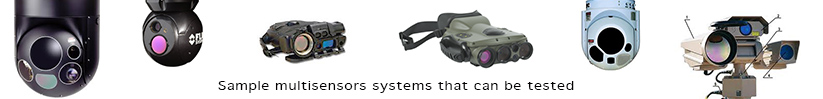
Inframet manufactures test stations capable to do all boresight tasks listed above.Multi-sensor EO system are the most difficult case for boresight. Therefore the term "Boresight station "in commercial section of this website means a station for boresight and basic tests of multi-sensor EO systems.Boresight of binocular night vision devices and laser range finders is to be done using separate test stations.