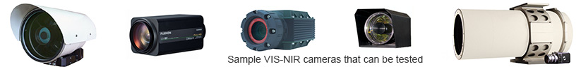
VIS-NIR cameras
Surveillance VIS-NIR cameras based on CCD/CMOS/ ICCD/ EMCCD/EBAPS imaging sensors sensitive in visible and near infrared range(VIS-NIR) are widely used in many long range surveillance applications as independent imagers or as part of a bigger multi-sensor surveillance systems. Majority of VIS-NIR cameras are used for day level applications but an increasing number of these cameras is used to enable surveillance in both night and day conditions. In both cases it is important to verify performance of these cameras under varying illumination conditions from very dark nights to ultra bright days. Important missions can fail due to too low sensitivity of VIS-NIR cameras at night conditions (dark, noisy images) or due to too low dynamic at ultra bright day conditions (saturated, blurred images). Next, it is important to use VIS-NIR cameras that generate high quality images in order to enable detection, recognitio.
Testing VIS-NIR cameras is needed to enable proper quality control, design improvements, maintenance and repairing. Proper testing is particularly important in case of expensive ultra long range cameras built using big optical zoom objectives.
Testing surveillance VIS-NIR cameras is not standardized. However, these cameras are typically characterized using the following parameters: Resolution, Minimal Resolvable Contrast, MTF, Distortion, FOV, Sensitivity, SNR, Noise Equivalent Input, Fixed Pattern Noise, Non Uniformity, 1/f noise, 3D Noise, Number of bad pixels and bad pixel localisation, Resposivity function (Responsivity, Linearity, Dynamic, Light Range), Color fidelity. More details in Educational section.
Inframet offers three test systems for testing VIS-NIR cameras: TVT, VINIS, and VLOF.
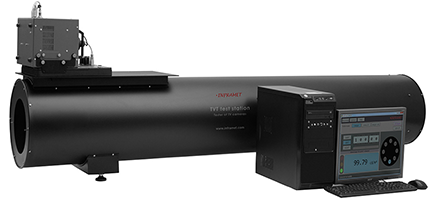
The TVT test station is a variable intensity image projector that projects images of some standard targets to the tested VIS-NIR camera. The tested camera generates copies of the projected images. Quality of the images generated by the camera is evaluated and its important characteristics are measured. The TVT test systems are built from the following blocks: DAL series calibrated light source, set of targets, rotary wheel, set of exchangeable refractive/reflective collimators, PC, frame grabber, TAS-V software, OS stage. The TVT test systems are recommended for testing VIS-NIR cameras used for medium/long distance surveillance. The TVT test systems can be delivered in several versions optimised to different applications of tested VIS-NIR cameras (day, night, day/night) and different camera design.
a)
b)
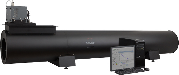
Fig.1. Photo of TVT test systems: a)TVT200, b)TVT300
TVT stations are characterized by a series of technical partameters that makes them superior on international market and TVT system have become favorite choice for both manufacturers, reseach teams or final users of long/medium range VIS-NIR cameras.
VINIS system can be treated as a simplified version of TVT system. In detail, it is a cost effective solution for testing VIS-NIR cameras and SWIR imagers. It is based on manual halogen light source coded as LS-MAH (non calibrated in basic version) in contrast to computerized calibrated DAL light source. Next, targets are manually inserted when in TVT system targets are automatically exchanged using MRW-8 rotary wheel. Finally, VINIS is typically delivered as an image projector without PC and test software (it is assumed that these blocks are delivered by customer if needed). All these changes in design have enabled significant price reduction comparing to typical TVT test system. At the same time LS-MAH light source is offered in a series of versions and this feature enables to optimize VINIS to different applications.
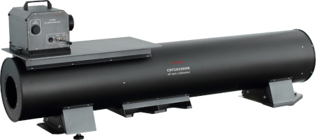
Fig.2. Photo of VINIS150 test system
The VLOF measuring set is a mobile variable distance measuring system that project images of a set of standard targets directly to the tested VIS/NIR camera. The tested camera generates a distorted copies of the projected images. Quality of the images generated by the VIS-NIR camera is evaluated and its important characteristics are measured.
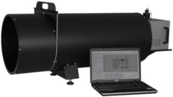
Fig.3. Photo of VLOF test system
Learn more:
- Data sheets: TVT, VINIS, VLOF
- Customer questionaires for systems for testing VIS-NIR cameras
- Recommendations on environmental conditions for Inframet test systems
- Educational section
- Inframet Info section
- Newsletter
- Contact INFRAMET